Joe Chipman continues to work on the Hermit DeLuxe and is giving us an update on the electrical. He has taken lots of great pictures to help you learn. Be sure and check out the electrical diagrams at the bottom of the post. This information will be included in the next update of the Hermit DeLuxe plans. I’ll let Joe take over and explain what he is doing.
I have been working right along as time and building funds would allow. So far I have the high voltage wiring complete and a good start on the low voltage. I have the 30a 240vac and 20a 120vac weather proof electrical connection mounted exterior rear of the Hermit DeLuxe with a 20a 120vac 100ft extension cord plugged in to the grid. The 30a 240vac electrical connection comes from the exterior junction box and goes to the main 240vac panel in the front of Hermit DeLuxe. The 20a 120ac electrical connection comes from the exterior box and goes to the inverter switching box tied though for now and to the main 240vac panel, and with the transfer switch the main 240vac electrical panel can be feed by the 30a 240vac feed or the 20a 120vac feed. Keep in mind the 20a 120vac feed can be grid or the inverter when finished.

The four 15a 120vac electrical curcuits wired out of the main 240vac panel, #1 main lighting and upper bunk receptacles, #2 Desk receptacles and lighting, #3 Kitchen receptacles, #4 Ref receptacle and rangehood. Main lighting includes main light switched from exterior door, kicthen sink and main bunk, sink light switched from kitchen sink, kitchen undercounter lights switched from kitchen sink, bathroom light and exhaust fan switched from front wall next to bathroom, undercounter light switched from workbench left side, workbench receptacles, upper bunk receptacles, upeer bunk light switched from ceiling next to exhaust fan, exterior light over exterior door switched at exterior door, exterior gfci receptacle next to exterior door. Desk circuit includes (7) desk receptacles, exhaust fan and lighting system above desk switched right of desk window, receptacle right of main bunk window half switched at main bunk. Kitchen circuit includes (2) above counter kitchen receptacles. Ref circuit includes receptacle for ref and a wire out for the rangehood.

I have a 20a 120vac receptacle under the kitchen sink for electric water heater, 120vac receptacle under window next to main bunk for air conditioner and recessed electric heater next to exterior door, fed from the exterior junction box, grid feed only.
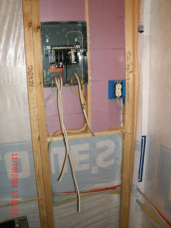
The 12vdc system is still a work in progress, but I do have wires run for five circuits. #1 A 12dc receptacle under kitchen sink for water heater. #2 A 12vdc receptacle under kitchen counter for ref. #3 A 12vdc receptacle obove desk left of window. #4 Upper bunk and work counter 12vdc receptacles. #5 12vdc main lighting switched at exterior door. The future 12vdc main electrical panel will be under the desk, right side wall, recessed mounted with a 1 1/4″ pvc pipe out to the gell cell batteries in battery box under desk, rear wall. A 3/4″ pvc out of main 12vdc panel up to a exterior junction box under solar panels on south facing exterior wall for solar panels electrical connection to the solar panel disconnect. Solar panel disconnect, charge controller, grid powered battery charger and 1000w sine wave inverter with automatic transfer switch will be surface mounted under desk next to main 12vdc panel. I hope to mount solar panels high on exterior wall with hinges to make a roof for a future porch, or mounted flat to wall for high winds or towing.
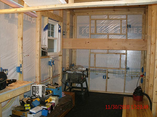
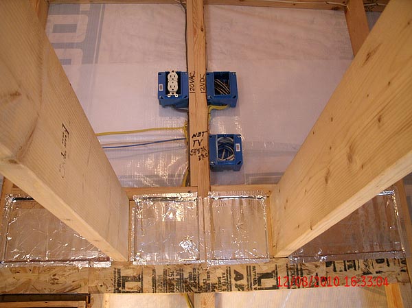
I have installed a antenna/network junction box above desk left wall with 1″ pvc pipe to exterior box high on left wall above desk for future antenna wires, (tv, wifi, cb, etc). I have antenna/network wires coming from main junction box to right side above desk and to upper bunk entertainment area.

I wired for surround sound in main area of Hermit DeLuxe and a separate sound system for upper bunk area.
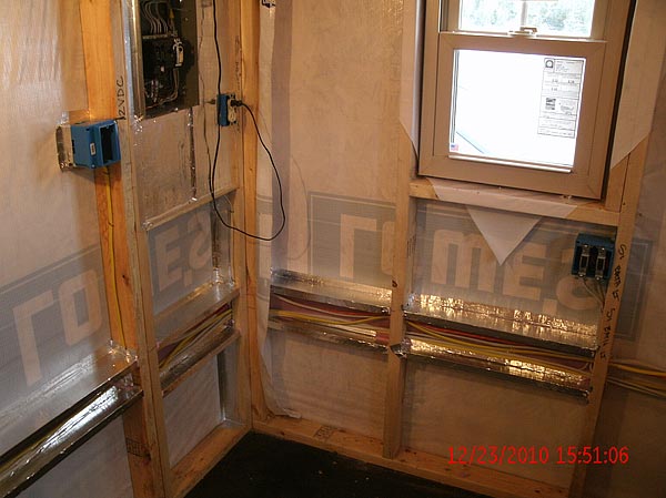
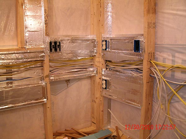
After the wires where in place I started installing insulation in ceiling and walls. I install 3/4″ R-4 foam insulation in ceiling completing sealing all joints with foil tape, I plan to finish ceiling with foil faced R-13 fiberglass insulation for a total of R-17. I have installed foam insulation in odd spaces around wires, boxes and electric panels and sealed with foil tape and plan to finish with R-13 fiberglass insulation.
Work will continue though the winter as building funds and time come available.
The Hermit DeLuxe Plans $27




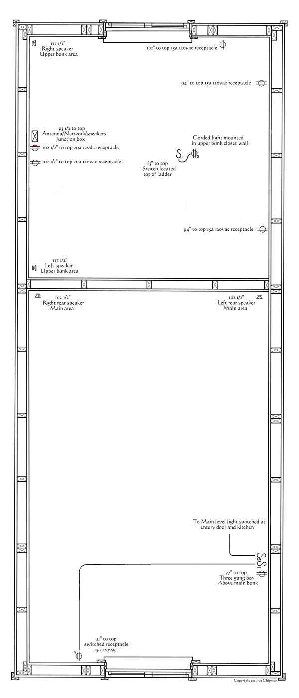

Swell schematics!
Maybe it was just a girl thing, but all those detailed wiring talk just made me cross eyed and confused. It looks great though.
I am sorry Margaret, I may got a little more detailed then needed. I always tend to go over board with with my wiring in all my projects. Thank you for your comment.
The Hermit DeLuxe
Joe Chipman
Now that we know where the zip tie stash is we can stage a raid…
Coming along nicely… Looking forward to the finished HD.
Ok, I see the house wrap, but why is there not plywood or OSB between the house wrap and the 2X4 studs? I do not understand…please explain…
I installed the Tyvak housewrap directly to the studs and then the osb siding as a final layer, trying to keep the weight and cost down.
The Hermit DeLuxe
Joe Chipman
Joe, great job it is very informative. Thanks for taking the time to post this.
It looks like you have some sort of foil conduit runs. Can you explain what this is?
I used 3/4″ foam and foil tape to make a gutter for the wires which I will fill with spray foam and trim flush with front of stud when cured.
The Hermit DeLuxe
Joe Chipman
Joe. Nice drawings. What software are you using for this project?
I draw them the old fashion way with my drafting set, paper and pencil and scan the drawings into Adobe PhotoDeLuxe Business Edition 1.1.
I Clean, edit and add text to my drawings and save as a Page size jpegs. Then using Open Office 3.1 draw I convert the individual jegs to one PDF file.
The Hermit DeLuxe
Joe Chipman
This is illustrative of “no matter how easy it looks in my brain, there are thousands of little details to get done I haven’t thought of yet.”
I wish my house was this well wired! There will be no need for any extension cord ‘octopus’ messes in this place.
Great detail, great pictures! Nice informative article, I love it when people share what they are doing in enough detail that you could use it to figure out how to do it your self.
Even better is following the progress through the steps, and please share when you think you would do some thing differently next time, so we can learn from your mistakes.
I cant wait to see how it comes out, thanks for sharing.
Great job. I do however have on thing to pick at. I’m pretty sure that the National Electric Code doesn’t permit wire joints in a panel. Ours doesn’t here in Canada.
I got caught short with a couple of homeruns after I moved the panel up a little. The code reads the same here, but mistakes happen and most electrical inspectors understand.
The Hermit DeLuxe
Joe chipman